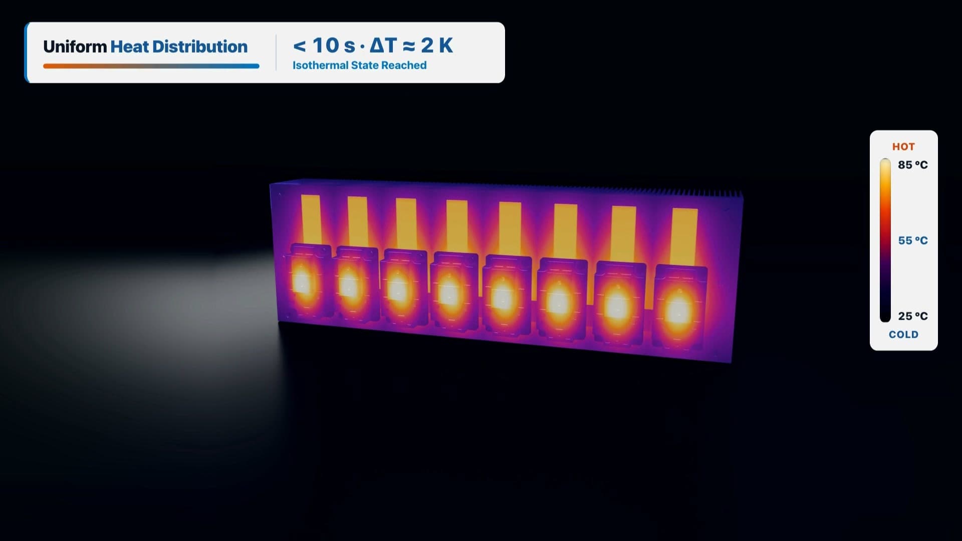
ALVC Two-Phase Cooling Wall for High-Power IGBTs: Why You Should Wait 10 Seconds Before Adding a Pump
Every power electronics project eventually hits the same thermal crossroads: power density goes up, solid aluminum baseplates run into spreading resistance limits, and suddenly a clean cabinet design requires pumps, hoses, quick-disconnects, and a 20-year maintenance schedule.
In this architecture analysis, we replaced the conventional solid mounting plate behind eight high-power IGBT modules with a structural ALVC two-phase cooling wall (Aluminum Vapor Chamber Heat Spreader).
Key Thermal Benchmarks Under Load
- Rapid Thermal Spreading (< 10 s): Uniform heat distribution across the entire cooling wall within seconds of load step.
- Zero Local Hotspots (ΔT = 4.7 K): Isothermal surface temperature uniformity across the entire multi-module mounting plane.
- Closed Capillary Cycle: Thin-film evaporation at the heat source, rising vapor core, and passive capillary return inside micro-structured aluminum channels.
- Zero Moving Parts (0 W Pump Power): Hermetically friction-stir welded (FSW), 100% inline helium leak-tested, and maintenance-free over the system lifetime.
Why Heat Sink Fins Finally Work at Full Efficiency
With a conventional solid aluminum or copper baseplate, heat remains trapped directly beneath the IGBT modules while distant fin sections remain underutilized. By integrating an ALVC two-phase backplane, the entire mounting wall operates at nearly the same temperature—maximizing fin effectiveness and eliminating the need for active liquid cooling loops in many industrial drive, traction, and BESS inverter designs.
Interactive Online Calculator (Zero Login): Launch the ALVC Co-Engineering Studio (Heatsink & Vapor Chamber Sizer) →